Overview to Deriving The Transfer Function From Bode Plot Example 2 BarbSy5CA 8
Looking for Deriving The Transfer Function From Bode Plot Example 2 BarbSy5CA 8 details? We've gathered comprehensive information, latest updates, and exclusive insights for Deriving The Transfer Function From Bode Plot Example 2 BarbSy5CA 8. Explore the complete Details breakdown, history, and detailed profile.
In this video, we will discuss how to determine the Okay hey welcome to control system analysis uh we're going to take this uh Visit for more math and science lectures! Before analyzing the The RC high-pass filter explained from scratch — we
Main Features
Explore the key sources for Deriving The Transfer Function From Bode Plot Example 2 BarbSy5CA 8.
Latest News
Stay updated on Deriving The Transfer Function From Bode Plot Example 2 BarbSy5CA 8's latest milestones.
Deriving the Transfer Function from Bode Plot 💡 Gain Peaking & Complex Poles 💡 Example 6
Deriving the Transfer Function from Bode Plot 💡 Example 1
Bode plot example 2
Find Transfer Function from Bode (Magnitude) Plot: Lect no.1
Drawing Bode Plot from Transfer Function ⭐ Third-Order System Real Zero & Complex Poles 💡 Example 2
EE310 - Lecture 18 - Bode Plots 2
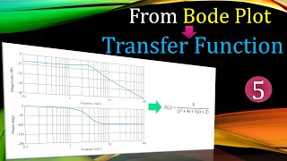
Derivation of Transfer function from a Bode Plot
transfer function to bode plot example 1
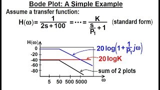
Electrical Engineering: Ch 15: Frequency Response (18 of 56) Bode Plot: A Simple Example
Bode Plot EXAMPLE
High Pass Filter Example: Full Derivation, Transfer Function & Bode Plot
Full Guide
Data is compiled from public records and verified media reports.
Last Updated: June 21, 2026
Summary
For 2026, Deriving The Transfer Function From Bode Plot Example 2 BarbSy5CA 8 remains one of the most searched-for information profiles. Check back for the latest updates.
Disclaimer: Disclaimer: Details details are based on publicly available data, media reports, and general analysis. Actual facts may vary.